3D Printed Vase Shroud
13 Nov 2017
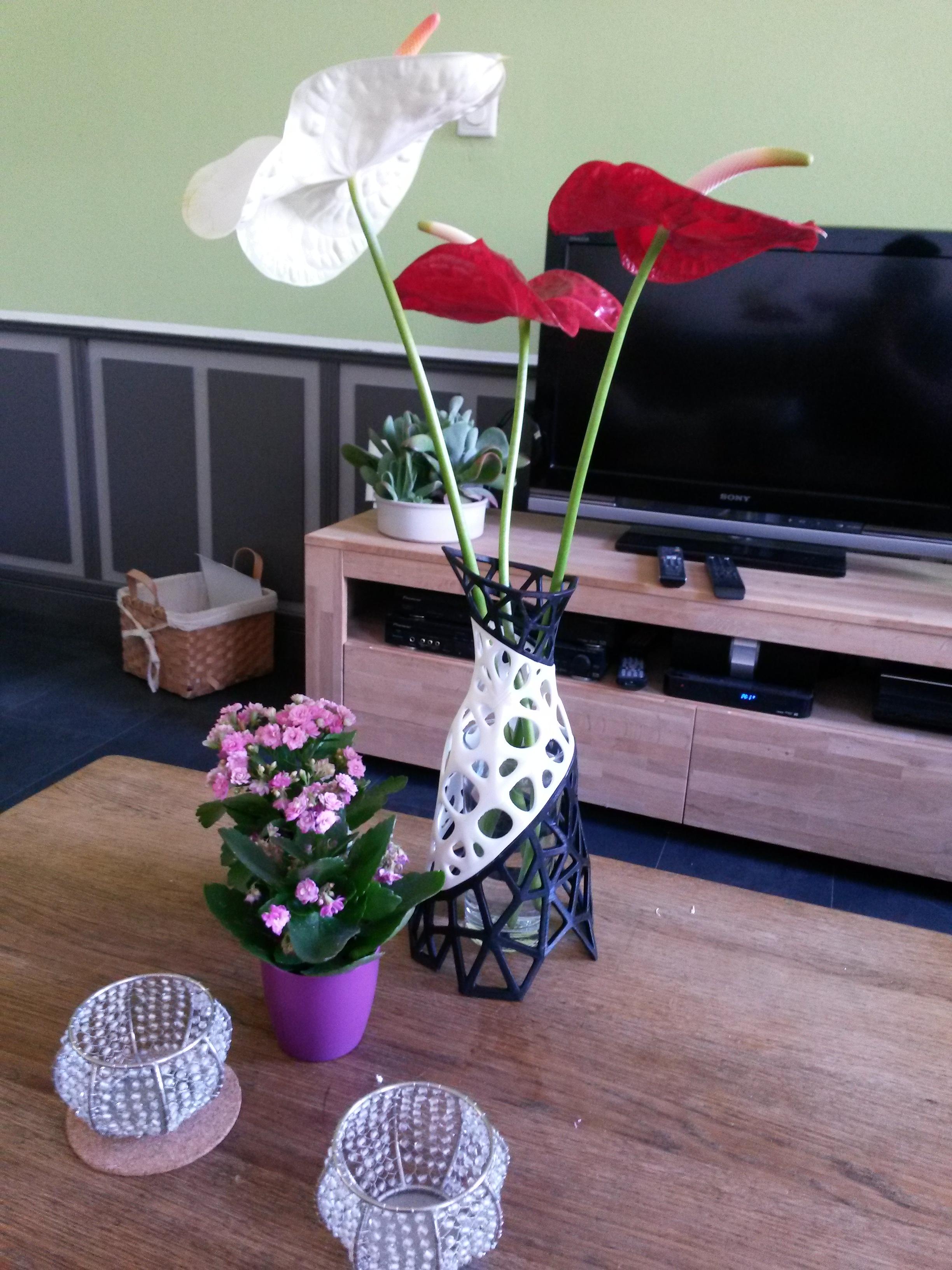
A few weeks ago I had my first encounter with 3D printing. Over the course of around 6 days I designed and printed a vase shroud as a gift for my mother’s birthday. Designed to be put over a big drinking glass in order to turn it into a functional vase.
 |
 |
 |
 |
These are some of the steps I’ve gone through while designing the vase. The very first iterations were meant to be two parts that slotted together on top of the glass. I experimented with some designs that mounted onto the rim of the glass and flowed down without supporting on the surface below. Unfortunately none of those attempts looked very good.
Once I had a talk with the people operating the printers to discuss practical constraints and options, I decided to drop the two-part design. I was hoping they had some experience with printing functional models that had to fit together, but unfortunately they did not. At that time the target date for this project was in about a week and a half, so there was very little time to run some experimental prints and iterate on a fastening method. Thankfully I got to take a look at the different types of filament they had available. This gave me the idea of printing in several parts with different styles.
 |
 |
The entire project was designed in my 3D modelling program of choice, Blender. The core of my workflow was modelling a rough shape, then shrinkwrapping another mesh to that shape and toying with modifiers and weightpainting on the shrinkwrapped mesh. This was a great way to prototype these kinds of models, however it wasn’t very practical when turning the rough mesh to an actual printed model. I was constantly afraid of applying the modifiers and breaking the procedural workflow that gave me so much freedom.
The three part design needed the connecting faces to match up properly. This was fairly difficult to achieve in this procedural approach. They were close, and some manual adjustments got them even closer, but in the end I opted to just cut the very high resolution mesh with a boolean modifier for a perfect edge.
In any future designs I would likely have used the procedural mesh as a base for manual retopology. I would still heavily depend on subsurf modelling to smooth out organic shapes like these, but a cleaner base model would have made part alignment and any other modifications much easier.
 |
 |
 |
 |
Tuesday afternoon we decided to print the smallest part of the model, the top part, overnight in final resolution to see how it would turn out. I was worried the small 4-6mm spokes would not be very sturdy, and the whole thing would break on a whim. Fortunately, PLA plastic is very sturdy stuff. The part came out looking incredibly good, and there was very little flex at all. I accidentally dropped it, and it was impossible to tell.
None of us had any idea of the capabilities of the printer (an Ultimaker 2) when it came to printing overhanging geometry. We decided to just generate supports everywhere just to be sure. I was expecting to spend a while sanding the thing anyway, so any damage to the model caused by the supports would just be included in the sanding. In the future I would test the printer’s abilities first while designing a model. In hindsight the model could probably have been tweaked a bit to cut down on extreme overhanging angles. This would have allowed for printing without, or with very little, support material. It would have saved a lot of time while printing, and the final result would have ended up much cleaner.
Unfortunately, while the first part was printing overnight, I learned that my timeline just moved up to the end of that week. I spent some time tinkering with print settings in Cura for the two bigger prints. With about 25 hours on each it would still be possible to finish those prints before the weekend. It did mean using the initial test print as a final result. Given the quality this was totally fine, it just meant working around the first print when I had wanted to tweak it some more.
 |
 |
 |
I was thinking of using little ball and socket connections to connect the parts. The bottom having little balls on top of the rim that would slot into holes on the underside of the part above it. The idea was that this would be easy to print with the intended orientations, and allow for easy alignment when gluing the parts together. In the end the connection from the bottom to the middle component does use this concept, while the middle to top connection just used little brackets to keep it aligned. This was because there was no more time to tweak and reprint the top part.
During final assembly I came to the conclusion that the ball/socket connection could have worked, but not at the exact size that I used. I was afraid it would mess up while printing if I placed them closer to the edge of the rim, but in hindsight it would likely have been fine as long as it had a margin of at least the nozzle size. As it stood that connection was just a little too deformed to be reliable. It was better than nothing, but not by a lot.
The connection between the middle and top part turned out to be completely useless. Don’t know what really went wrong there, they just didn’t help in the slightest.
 |
 |
 |
The amount of material lost on supports for the two bigger parts was quite staggering. The damage to the parts from support material was also more severe than expected. It was nowhere near bad enough to affect the strength of the print, but it would likely have resulted in very thin pieces if they were sanded flat. In the end it is still quite rough to the touch, but it isn’t very noticeable. The white part would probably have been better off if it had been cut in half vertically. I did design it symmetrically, and at some point did have them as two separate pieces.
 |
 |
 |
The two big prints did not come out flawless unfortunately. There are some shifted layers on one axis that are very noticeable up close. Fortunately, after a lot of sanding most of it isn’t so bad. After doing some more research I suspect it might have something to do with the tightness of one of the axis pulley belts.
 |
 |
 |
 |
Sanding and assembly were great fun. Seeing the entire thing come together was very satisfying. However, PLA plastic is a pain in the ass to sand due to its hardness, and I would recommend against hand sanding this material. You’ll probably want to get some powered assistance if you’re doing anything more than just touch-ups. The problem areas caused by the support material were left fairly coarse, as again it probably would have meant taking off more than reasonable amounts of material. It would not have surprised me if it’d break through the outer surface of the print.
For very polished final objects you’re probably better off coating it in some kind of resin and sanding it smooth. For high precision prints this might prove to be challenging when it comes to tolerances, but with some trial and error it’s probably possible to find a balance between printing tolerance and resin coat thickness.